Key Points
- Circle systems permit a patient to rebreathe expired gas after the removal of carbon dioxide (CO2) through an absorptive filter, allowing for the conservation of heat, humidity, and volatile anesthetic agents.
- Noncircle systems have separate pathways for inspired and exhaled gases and have minimal to no mixing of fresh gas and expired gas.
- Portable ventilation devices are used when transporting patients in need of ventilation or in emergency scenarios.
Introduction
- Anesthesia breathing systems are made up of components that connect the patient to the anesthesia machine to deliver oxygen and anesthetic gases to the patient and eliminate CO2. Most breathing systems have similar components but are configured differently.1,2
- The adjustable pressure limiting (APL) valve is a one-way, spring-loaded valve that allows the maintenance of variable pressures within the anesthesia breathing system and control of the patient’s airway pressures.1
- The reservoir bag allows the collection of fresh gas flow (FGF) during expiration and monitoring of the breathing pattern in a spontaneously ventilating patient. They are usually made of rubber or plastic and come in a range of sizes from 0.5 to 3 liters. Most adult systems use a 2-liter reservoir bag.1
- The inspiratory limb allows passage of FGF to the patient and the expiratory limb allows passage of expired gas from the patient. While the length of the tubing varies, the diameter of the tubing is standard across all systems: 22 mm for adults and 18 mm for children.1
- The position of the various components and the presence of valves determine the functional characteristics and resistance of the different anesthesia breathing systems.
- Circle or rebreathing systems include a CO2 absorber and unidirectional valves, while nonrebreathing systems do not include a CO2 absorber.
Circle Systems
- The circle system is the most commonly used anesthesia breathing system. The components of a circle system are (Figure 1)1-3
- CO2 absorbent (i.e., soda lime)
- Two unidirectional valves (inspiratory and expiratory)
- Fresh gas entry
- Y-piece connecting to the patient
- Reservoir bag
- APL valve
- Low resistance interconnecting tubing
- The defining design element of a circle system is a CO2 absorber that effectively eliminates CO2 from exhaled gases, allowing rebreathing. This capability reduces the need for high FGF and enables the conservation of heat and inhaled anesthetic agents (Figure 1).
- A Y-piece septation prevents the mixing of fresh and exhaled gases and minimizes dead space in the circuit. Exhaled gas travels through the Y-piece to an APL valve and reservoir bag before being filtered and returned to the patient.1-3
- The apparatus dead space in a circle system is minimal and is limited to the area distal to the point of inspiratory and expiratory gas mixing at the Y-piece.
- The unidirectional valves in circle systems function as check valves and increase the resistance to breathing. The expiratory valve can also become stuck by water vapor, leading to an increase in dead space. Malfunction of either unidirectional valve may allow rebreathing of CO2, resulting in hypercarbia.
- During the initial 5-10 minutes of use, a high FGF is required to equilibrate the breathing system with the desired mixture, after which low FGF of 0.5 liters per minute can be used.

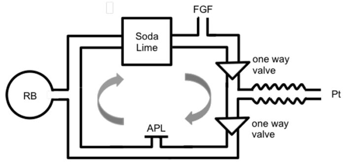
Figure 1. Components of a circle system. Source: Tsim P, Howatson A. Breathing systems in anaesthesia. WFSA Anesthesia Tutorial of the Week. 2016. CC BYNC ND 4.0. Link
- Advantages of a circle system3,4
- Respiratory support can be adjusted to optimize the FGF rate and volume of volatile anesthetic agents consumed.
- Reduction in operating room pollution compared to other systems
- Conservation of moisture, heat, and anesthetic
- Disadvantages of a circle system3,4
- Increased complexity
- Multiple components with the potential for disconnection
- Increased resistance
- Potential for difficulty assessing fractional exhalation composition
- Potential to rebreathe CO2 in the event of exhausted CO2 absorption components
- Subclassifications
- A circle system can be closed or semi-closed. In a closed circle system, the APL valve is completely closed. while in a semi-closed system, the APL valve is open to allow excess gas to be removed from the system.1
- Closed circle systems allow for total rebreathing. These systems have demonstrated greater control in maintaining constant alveolar concentrations of anesthetic but require a deeper understanding of the uptake and distribution to operate. When low-flow anesthetic gases are used, the inflow of fresh gas can be titrated to match the patient’s oxygen consumption and anesthetic uptake.2,5
- Semi-closed systems allow for partial rebreathing and are the most common breathing systems in the United States.2,5
Noncircle Systems
- Noncircle systems include insufflation, open-drop anesthesia, and semi-open systems.
- Insufflation is analogous to “blow by,” where oxygen with or without anesthetic is blown into the patient’s airway without direct contact, such as via a face mask. This breathing system is primarily used in pediatric patients where mask placement may be resisted. Insufflation can also occur directly into the airway/ trachea via a device such as a bronchoscope.
- Open-drop anesthesia is the simplest breathing circuit and is no longer in use. Gauze soaked in anesthetic liquid, historically ether or chloroform is placed over a patient’s face. Inhalation causes vaporization of the anesthetic as air moves through the gauze, delivering highly unpredictable levels of anesthetic to the patient.2
- Semi-open systems or Mapleson circuits:
- The patient is connected to the system via a mask linked by corrugated tubing to a reservoir bag and an FGF inlet where mixed gas will be delivered without the presence of a CO2 absorber.
- The movement of fresh gas through the FGF inlet forces exhaled gas into the environment.
- These systems are generally referred to as Mapleson circuits and are separated into classes A-F depending on the position of the FGF inlet and APL valve.2,5 (Figure 2)
- While less complex than closed circuits, FGF requirements are higher which leads to greater gas waste, operating room pollution, and loss of heat and/or moisture.2,4,5
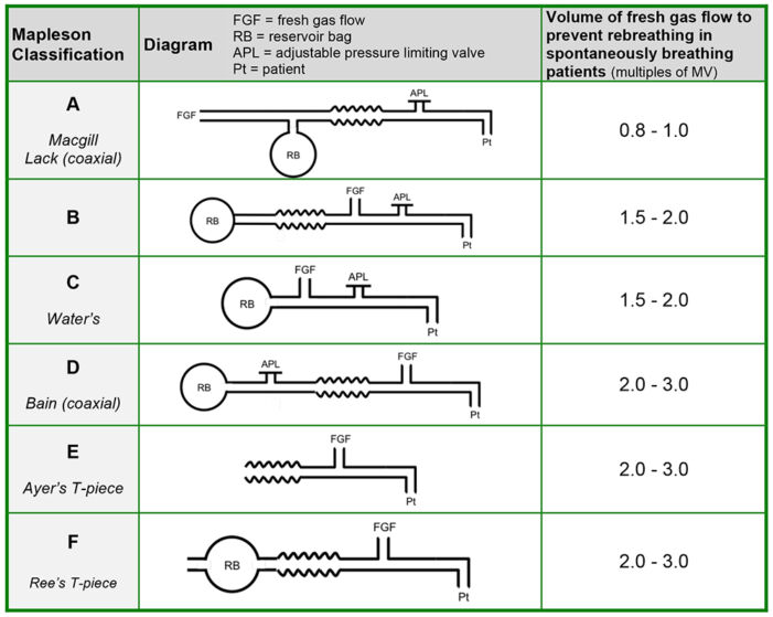
Figure 2. Mapleson circuits. Source: Tsim P, Howatson A. Breathing systems in anaesthesia. WFSA Anesthesia Tutorial of the Week. 2016. CC BYNC ND 4.0. Link
-
- The APL valve is close to the patient in Mapleson A, B, and C circuits, and the reservoir bag is on the opposite side of the circuit. Interchanging the position of the APL valve and the FGF inlet converts a Mapleson A circuit to a Mapleson D circuit. Mapleson E and F circuits do not have an APL valve.
- The Mapleson A circuit is the most efficient Mapleson circuit for spontaneous ventilation because an FGF equal to minute ventilation is sufficient to prevent rebreathing.1 The efficiency of Mapleson circuits (measured as the lowest FGF that prevents rebreathing) for spontaneous ventilation is A > D, F, E > C, B (mnemonic: A dog can bite)
- The Mapleson D circuit is most efficient for controlled ventilation because FGF forces alveolar air away from the patient and towards the APL valve. The efficiency of Mapleson circuits (measured as the lowest FGF that prevents rebreathing) for controlled ventilation is D, F, E > B, C > A (mnemonic: dog bite can ache)
- A commonly used configuration is the coaxial Mapleson D circuit or Bain system, where the fresh gas inlet tubing is inside the breathing circuit. FGF is delivered via the inner tube and the waste gases are removed via the outer tube. (Figure 3).1 This modification decreases the circuit’s bulk and retains heat and humidity better than a conventional Mapleson D circuit. A disadvantage of this coaxial system is the possibility of kinking or disconnection of the inner tubing resulting in the delivery of a hypoxic gas mixture.
- A Mapleson D circuit is often used for manual ventilation while transporting patients. A modified Mapleson D circuit can also be used to deliver continuous positive airway (CPAP) pressure to the nonventilated during one-lung ventilation.
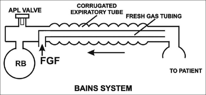
Figure 3. Bain’s modification of Mapelson D circuit. Source: Kaul TJ, et al. Mapelson breathing systems. Indian J Anaesth. 2013;57(5): 507-15. CC BY NC SA 3.0
-
- Advantages of Mapleson circuits
- Inexpensive, lightweight, and simple to use
- Low resistance circuits
- Changes in FGF result in rapid changes in inspiratory gas concentrations
- Disadvantages of Mapleson circuits
- Higher FGF needed to prevent rebreathing
- Loss of heat and humidity unless a coaxial system used
- Greater environmental pollution
- Advantages of Mapleson circuits
Portable Ventilation Devices
Self-Reinflating Portable Ventilation Devices (i.e., Ambu bags)
- Also known as bag-valve-mask devices, these include a self-inflating bag and a nonrebreathing valve that allows air within the bag to pass to the patient while blocking the expiratory port6 (Figure 4).
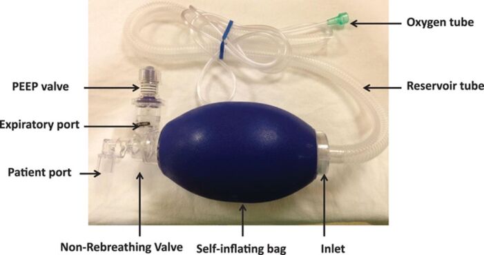
Figure 4. Parts of a self-inflating portable ventilation device. Used with permission from Sivco CS, Cherian VT. What every anesthesiologist should know about the manual resuscitation bag. A A Pract 2018;11:288-91. PubMed
- The nonrebreathing valve prevents mixture of expired and fresh gases in a self-inflating bag by allowing gas to escape into the atmosphere upon expiration. The valve closes during inspiration to prevent fresh gas from escaping, ensuring the patient receives the contents of only the self-inflating bag (Figure 5).
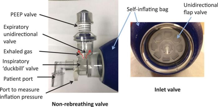
Figure 5. Closer view of the non-rebreathing valve. Used with permission from Sivco CS, Cherian VT. What every anesthesiologist should know about the manual resuscitation bag. A A Pract 2018;11:288-91. PubMed
- Manual compression of the self-inflating bag is needed to deliver oxygen during positive pressure ventilation.
- Passive oxygenation methods, such as administering oxygen through blowby or using a mask seal during spontaneous ventilation, cannot be achieved with self-inflating systems. This limitation arises because oxygen flow in self-inflating systems necessitates manual compression of the self-inflating bag.
- Rigidity gives the reservoir bag “memory,” and allows for spontaneous reexpansion during expiration.
- An external supplemental oxygen source can be used to deliver oxygen at different concentrations depending on the status of the patient. An oxygen flow of above 15 L/minutes is needed to attain close to 100% oxygen.6 The fraction of inspired concentration delivered to the patient is directly proportional to the oxygen inflow concentration and flow rates and inversely proportional to the minute ventilation delivered to the patient.
- A tight seal to a patient’s face during self-reinflation is imperative to ensuring pure oxygen is delivered on the next administered breath as to not entrain room air and dilute the inspired oxygen concentration.
- While ventilating a patient with an endotracheal tube, the squeezing of the bag should be synchronized to the inspiratory efforts of the patient.
- This device cannot be used to deliver CPAP to the patient.6 However, an adjustable, spring-loaded disk valve attached at the expiratory port can be used to provide positive end-expiratory pressure up to 20 cm H2O (Figure 4). This is only effective with a tight-fitting facemask or a cuffed endotracheal tube.
- Self-inflating bags can facilitate resuscitation using room air, even when a medical gas oxygen source is unavailable.
Non-Self-Reinflating Breathing Devices
- Also called a hyperinflation system
- Must receive a constant flow from an oxygen source to maintain inflation
- A summary of the different anesthesia breathing systems is listed in Table 1.
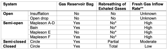
Table 1. Summary of breathing systems.
*No rebreathing only when the FGF is adequate
**High: greater than 6 L/min, moderate: 3-6 L/min, low: 0.3-0.5 L/min
References
- Garrett A, Stahl DL. Anesthesia breathing systems. StatPearls. Treasure Island, FL. StatPearls Publishing. 2023. Link
- Parthasarathy S. The closed circuit and the low flow systems. Indian J Anaesth. 2013; 57: 516-24. PubMed
- Sivco CS, Cherian VT. What every anesthesiologist should know about the manual resuscitation bag. AA Pract. 2018;11: 288-91. PubMed
- Nakae Y, Miyable M, Sonoda H, et al. Comparison of the Jackson-Rees circuit, the pediatric circule, and the MERA F breathing system for pediatric anesthesia Anesth Analg. 1996;83: 488-92. PubMed
- Weigel WA, Murray WB. Detecting unidirectional valve incompetence by the modified pressure decline methos. Anesth Analg. 2005;100: 1723-7. PubMed
- Baum J. Anesthesia systems. Anaesthetist. 1987; 36:393-9. PubMed
- McQuade D, Miller MR, Hayes-Bradley C. Addition of nasal cannula can either impair or enhance preoxygenation with a bag valve mask: A randomized crossover design study comparing oxygen flow rates. Anesth Analg. 2018; 126: 1214-8. PubMed
- Conway CM. Anaesthetic breathing systems. Br J Anaesth. 1985; 57:649-57. PubMed
- Grauman S, Johansson J, Drevhammar T. Large variations of oxygen delivery in self-inflating resuscitation bags used for preoxygenation- a mechanical simulation. Scan J Trauma Resusc Emerg Med. 2021;29(1):98. PubMed
Other References
- Bechtel A, Chiao S. Breathing circuits. OA Keys to the Cart. 2017. Link
Copyright Information

This work is licensed under a Creative Commons Attribution-NonCommercial-NoDerivatives 4.0 International License.