Key Points
- Ultrasound is used in multiple subspecialties of anesthesia.
- Varying the parameters of the transducer and its interpretation of the sound wave data allows customization for structures of varying density and depth.
Introduction
- Ultrasound is integral in regional anesthesia for guidance of peripheral nerve blocks and catheters, in cardiac anesthesia for transesophageal echocardiography, and in multiple aspects of perioperative anesthesia for multiorgan diagnostic point-of-care ultrasound and for procedural guidance of vascular access (e.g., arterial, central, and peripheral catheters).
- Electricity excites piezoelectric crystals within the ultrasound probe which emit high-frequency sound waves.1,2
- These sound (or pressure) waves propagate through tissue, which scatter ultrasound waves in multiple directions, reflecting some of the energy back to the ultrasound transducer.
- The energy that reflects back to the transducer mechanically stresses the transducer’s piezoelectric crystals causing them to generate electrical signals.
- The electrical signals are converted by software in the ultrasound machine into an image that represents the varying densities of the underlying structures.1,2,4
Resolution
- Two types of resolution: spatial and temporal
- Spatial resolution is akin to image quality, specifically the ability to discern the difference between two structures.
- Spatial resolution has two aspects: axial (or longitudinal) and lateral (Figure 1).
- Increased frequency bandwidth improves axial resolution (i.e., whether two objects are resolvable in the direction parallel to the sound beam).
- Both beam width and frequency bandwidth impart lateral resolution (i.e., whether two objects are resolvable in the direction perpendicular to the sound beam).

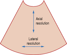
Figure 1. Axial and lateral resolution on an ultrasound image. Source: radiologykey.com/resolution
-
- Spatial resolution is determined by the spatial pulse length (wavelength x number of cycles in a pulse of ultrasound) (Figure 2 and 3).
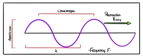
Figure 2. Properties of an ultrasound wave. Reprinted with permission from David Convissar, www.Countbackwardsfrom10.com
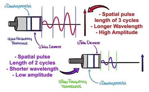
Figure 3. Low-frequency transducer: long spatial pulse length, low axial resolution. High-frequency transducer: shorter pulse length, higher axial resolution. Reprinted with permission from David Convissar, www.Countbackwardsfrom10.com
Temporal resolution
- The ability to distinguish between events in time, e.g., in rapidly moving heart structures during a cardiac cycle.
- An ultrasound clip is generated as a series of frames over time, and each frame is created from repeated pulses that form scan lines.
- Temporal resolution is equal to the time from the beginning of one frame to the next.
Frequency
- The frequency of an ultrasound beam (f) is inversely proportional to its wavelength (λ) and varies with the specific velocity of sound in a given tissue, by the formula λ = c / f
- Frequency, resolution and depth (Figure 4)
- Shorter wavelengths → higher frequencies → higher resolution images, but shallower penetration
- Longer wavelengths → lower frequencies → lower resolution images, but penetrate deeper
- Ultrasonography uses frequencies between 2-18 MHz.
- High-frequency (8-15 MHz) linear transducers penetrate shallow structures (target 3-4cm) and offer higher resolution.3
- Low-frequency (3-5 MHz) curvilinear transducers penetrate deeper structures (target >5cm) and yield lower resolution.3
- Once a transducer is selected, further adjustment within the frequency range can be made to optimize images.
Depth
- Depth of penetration depends on frequency as discussed above.
- This can be adjusted with each transducer selected.
- Similar to aperture on a camera, the ultrasound beam can be focused, which increases resolution at a certain depth (Figure 4).
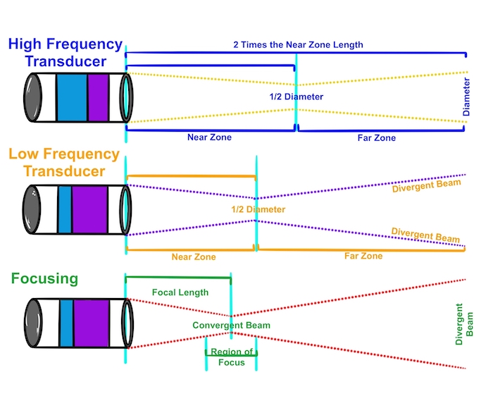
Figure 4. Higher-frequency transducers: narrow beam width, longer near-zone length. Lower-frequency transducers: wider beam width, shorter near-zone length. Reprinted with permission from David Convissar, www.Countbackwardsfrom10.com
Resonance
- Acoustic resonance: system amplifies sound waves whose frequencies are the same as its own natural frequencies of vibration.
- May result in a reverberation artifact (i.e., repeating hyperechoic structures such as a needle) which can occur with hyperresonance2 (Figure 5, 6, and 7).
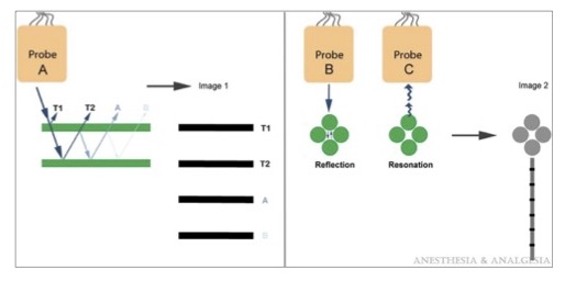
Figure 5. The mechanism of reverberation is shown using probe A. T1 and T2 represent the borders of the reflective object and their corresponding image on the display. Image 1, line A occurs when the ultrasound pulse makes 1 additional reflection after T2. Image 1, line B occurs when the ultrasound pulse makes 2 additional reflections. Ring-down artifacts occur in the presence of gas collections, from reverberation of the ultrasound within or between the gas collection (probe B) or resonation as the ultrasound beam passes through them (probe C). Reproduced with permission from Le HT, et al. Imaging Artifacts in Echocardiography. Anesth Analg. 2016.4
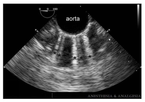
Figure 6. Multiple comet-tail artifacts (black asterisks) radiate from the anterior wall of the calcified descending aorta. Reproduced with permission from Le HT, et al. Imaging Artifacts in Echocardiography. Anesth Analg. 2016.4
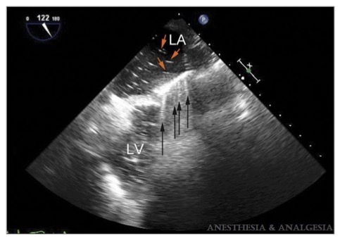
Figure 7. Ring-down artifacts (black arrows) are seen from the midesophageal long-axis view before separation from cardiopulmonary bypass. Residual air bubbles (red arrows) inside the left atrium (LA) before separation from bypass create a ring-down artifact that appears as a series of rays radiating from the anterior wall of the left atrium. LV = left ventricle. Reproduced with permission from Le HT, et al. Imaging Artifacts in Echocardiography. Anesth Analg. 2016.4
References
- Sites BD, Brull R, Chan VW, et al. Artifacts and pitfall errors associated with ultrasound-guided regional anesthesia. Part 1: understanding the basic principles of ultrasound physics and machine operations. Reg Anesth Pain Med. 2007; 32: 412-418. PubMed
- Le, HT, Hangiandreou N,Timmerman R, et al. Imaging Artifacts in Echocardiography. Anesth Analg. 2016;122(3):633-46. PubMed
- Grant SA, Auyong DB. Basic Principles of Ultrasound Guided Nerve Block. In: Ultrasound Guided Regional Anesthesia. 2e. Oxford University Press. 2017.
- Alexander Ng, Justiaan Swanevelder. Resolution in ultrasound imaging. BJA Education. 2011;11(5):186-192. Link
- Yap EN, Gray AT. Peripheral Nerve Blocks. In: Basics of Anesthesia. 7e. Eds: Pardo Jr. MC, Miller RD. Elsevier. 2018.
- Briggs ER. Regional Anesthesia. In Pocket Anesthesia. 3e. Eds: Urman RD, Ehrenfeld JM. Wolters Kluver. 2017.
- Khan MF. Ultrasound Guidance for Regional Anesthesia. In: Anesthesia Guide. Eds: Atchabahian A, Gupta R. McGraw-Hill. 2013.
Other References
Copyright Information

This work is licensed under a Creative Commons Attribution-NonCommercial-NoDerivatives 4.0 International License.